CAD analysis that reads the geometry directly
Glintify reads manufacturing data directly from your CAD file, with no forms. Holes, bends, contours, weld seams, tubes and purchased parts are classified and become input to the calculation. When there is a PDF drawing, requirements such as material, tolerances and surface requirements are read in and linked to the model for review.
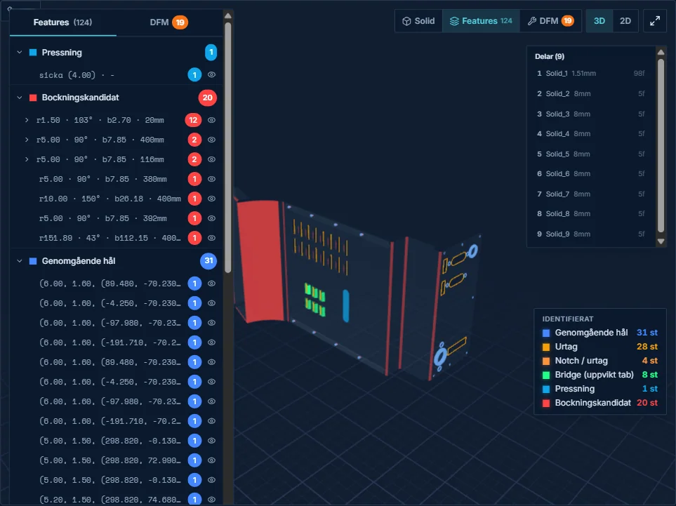
Manufacturing features, every detail counts
The system analyzes the geometry in depth and classifies every feature by manufacturing logic, not just by shape.
Geometry
Bounding box, sheet thickness, solid volume and surface area, all from the CAD file with no forms.
Holes and piercings
Through holes, blind holes, threaded holes, counterbores and formed features are classified by type with diameter and position.
Contours
Outer and inner contours are measured directly from the geometry. Contour length gives exact cut time per process.
Pipes and profiles
Round tube (OD, ID, wall), RHS, SHS and box profiles with cross-section dimensions and centerline length.
Bends
Standard bends, hem bends, bridges and special bends with degree, radius, axis and bend length.
Weld seams
Seams between the parts of an assembly with joint family, length and proposed throat a. Modelled weld beads are measured from their own geometry.
Purchased parts
Press nuts, press studs, standoffs, weld nuts, weld studs and rivet nuts are recognised by their designation in the STEP file and priced as purchases, never as a manufactured part.
Drawing requirements
Material, thickness, tolerances, surface requirements, weld symbols and threads from the PDF drawing are collected with a reference to the sheet and shown on the model for review.
Multi-part analysis
Assemblies with multiple solids are analyzed per component. Each part gets its own feature detection, DFM check and price calculation. The system understands which parts are welded together and which are separate items.
- Each solid is analyzed individually
- Contact surfaces between parts become weld seams with length
- Purchased parts are separated from manufactured parts
- BOM is generated automatically
- Per-part price with assembly cost
Which CAD formats are supported?
Glintify works with the most common neutral formats. More formats are added continuously.
| Format | Status |
|---|---|
| STEP (AP203/AP214/AP242) | Fully supported |
| IGES | Fully supported |
| STL | Support in v2 |
| DXF | Support in v2 |
| PDF drawing | Read and linked to STEP |
Have another format?
We evaluate new formats continuously. Contact us if your format is missing, we build support if it is technically possible.
Detection in three dimensions, not just a 2D projection
Our engine works on the original 3D geometry, not a flattened 2D drawing. That means depth, volume, angles and spatial relationships are preserved, and every feature gets the right classification from the start.
Depth and volume
Blind holes are distinguished from through holes. Counterbore angle and depth are measured directly.
Angles and radii
Bend angles, radii and K-factor per bend, straight from the 3D geometry.
Contact surfaces
Surfaces where solids meet become weld seams with joint family and length, ready for the estimator's confirmation.
Spatial orientation
Features are positioned in 3D space for exact bend sequence and fixturing.
Keep exploring the platform
Sending in a file for a quote? choose the right CAD data for a quote and see what needs to be added.
Comparing systems? what a quoting system should read from a STEP file.
Try it on your own part
Send a STEP file from a typical product. We run the analysis and show exactly which features the system finds.
Book an analysis