What is bending?
Bending is the step where the flat sheet becomes a part with flanges. Cutting gives the contour. Bending gives the shape. Without that distinction it is easy to price a U-profile as if it were a flat washer.
In sheet metal manufacturing, bending is usually done in a press brake: a punch pushes the sheet into a die with a V-opening. A robotised press brake uses the same bending principle, but the robot handles the part. A panel bending centre works on a different principle, normally with a manipulator and bending blades rather than punch and V-die. What you quote is therefore not a bend as an abstract concept, but a concrete chain: geometry, tooling, force, machine, time and staffing.
A bent part carries more than the angle. It carries bend length, number of bends, whether tooling must be changed, whether one person is enough to hold the blank, and whether any machine in the shop can even run the part. That chain decides whether the quote holds once the part reaches production.
The terms in brief
- Bending
- The operation where a flat sheet takes shape along one or more bend lines, usually in a press brake, panel bender or robot cell.
- Bending technique
- How force and tooling form the sheet. In a press brake: air bending, bottoming or coining. The technique sets radius, tonnage and how sensitive the angle is to springback.
- Bending chart
- A table, sometimes called a V-table, that links thickness and material to V-opening, approximate inside radius, minimum flange and often tonnage.
- Air bending
- The most common press brake technique. The punch pushes the sheet into the V-opening without pressing it to the bottom. The radius is set mainly by the V-opening, not by the punch tip.
- Robot bending
- A press brake cell where a robot handles the part between bends. The bending principle is the same as in a manual press brake. The economic gain usually sits in automated handling, a stable process and low staffing, not automatically in shorter cycle time.
- Panel bender
- A bending centre that forms the sheet with a manipulator and bending blades, not with punch and V-die. Universal tooling and machine-side handling make it a different machine type from the press brake.
- Bent parts
- Parts whose price and lead time are driven by bend length, number of bends, tool changes, handling and whether the part fits the presses you own.
Bending technique: three ways to form the same angle
Bending technique is not a brand. It is the choice of how far the punch travels and what actually sets the angle. Three techniques occur in a press brake. They do not give the same radius, the same tonnage or the same tooling needs.
| Technique | What happens | When it is used | What it costs you |
|---|---|---|---|
| Air bending | The punch lowers the sheet part way into the V-opening. Contact is on the die shoulders, not the bottom. | The standard choice for most bent parts in thin and medium gauge sheet. | Lowest force, least wear, one V-opening can cover several angles. Requires springback compensation. |
| Bottoming | The sheet is pressed down against the die flanks so the angle is locked more by the tool shape. | When the angle tolerance is tighter than air bending can hold with available compensation. | Higher tonnage, more wear and usually one tool per angle. |
| Coining | Punch and die squeeze the material so the angle is set by the tool. | Small parts with very tight angle requirements, rarely a first choice in a general press brake cell. | Highest force, highest tool wear, worst economics in mixed production. |
The table scrolls sideways on mobile.
Air bending is the starting point in most press brake calculations, and it is the technique the force model below applies to. In air bending the inside radius is in practice determined by the V-opening, as long as the punch is sharper than the radius the opening produces. Draw an R1 in CAD and run it in a 24 mm V-opening and you will not get R1. You get the radius the tool gives.
That is also why the blank size cannot be calculated on the drawing's desired radius if production runs another one. How the neutral axis and the K-factor then give flat length is covered in the article on K-factor and flat length according to DIN 6935.
How to read a bending chart
A bending chart, sometimes called a V-table, is the estimator's quick map. For a given thickness it answers four questions: which V-opening you start in, roughly which inside radius air bending gives, how short the flange may be, and how much tonnage one metre of bend requires.
The chart is a starting value. It is not a standard and it is not your tool library. Many companies start around eight times thickness for thin sheet and move up as the material gets heavier, because too narrow a V-opening drives force and wears the tooling. Stainless, aluminium and high-strength steels move both radius requirements and tonnage even at the same thickness.
The numbers below are an illustrative example for air bending in mild steel, not a production standard. The inside radius is set as roughly V/6 and the minimum flange as roughly 0.77 × V. A real tool library and the tool maker's data always take precedence.
| Thickness t (mm) | Example V (mm) | Approx. Ri (mm) | Approx. minimum flange (mm) |
|---|---|---|---|
| 1.0 | 8 | 1.3 | 6 |
| 1.5 | 12 | 2.0 | 9 |
| 2.0 | 16 | 2.7 | 12 |
| 3.0 | 24 | 4.0 | 18 |
| 4.0 | 32 | 5.3 | 25 |
| 5.0 | 40 | 6.7 | 31 |
| 6.0 | 50 | 8.3 | 39 |
Illustrative example for air bending in a press brake. Not DIN, not Glintify default values and not a replacement for your own tooling.
This is how the chart is used in practice. You have a 3 mm part. The chart points to a 24 mm V-opening. Do you have that die in house, and is it long enough for the longest bend? Does it give a flange the tool can still grip? And can the material take the inside radius the opening gives, or do you have to go up in V, down in force but up in minimum flange?
The last step is tonnage. For air bending in a press brake, a common approximate model for the force requirement is:
P [kN/m] = 1.42 · Rm · t² / V
Force per metre grows with tensile strength and with the square of thickness, and falls with a wider V-opening. Multiply by the bend length in metres. A 3 mm sheet with Rm 360 MPa, bent 800 mm in a 24 mm V, gives about 192 kN/m. Over 0.8 m that is roughly 153 kN, and with a ten percent reserve about 169 kN. The same bend in a material with Rm 700 MPa needs close to double. Real tool and machine tables, as well as your own validated data, take precedence over the generic model.
Sheet thickness is a common starting point for the V selection, often in the range 6-8 times thickness and sometimes around 8x. That is a starting value, not an absolute rule. The final choice is also affected by desired inside radius, minimum flange, material, strength, available tooling, tonnage and part geometry.
A bending chart without a material column is therefore incomplete. Two 3 mm sheets, one in soft deep-drawing steel and one in high-strength steel, can land on the same V-opening and still require a different press and a different punch.
What drives the price of bent parts
Bent parts rarely become expensive because the angle is 90 degrees. They become expensive because time, tooling and handling pile up around the angle. Five factors are visible already in the quote basis.
| Factor | What happens | What the estimator can influence |
|---|---|---|
| Number of bends | Every bend is a cycle. More bends mean more time, more repositioning and more frequent tool changes. | Ask whether two adjacent bends can be merged, or whether one V-opening covers them all. |
| Bend length | Force scales with length. The longest bend decides which press is even a candidate. | Check that the longest capable press in the shop is enough before you promise delivery. |
| Tool changes | Different radii or V-openings force a setup mid-part. That setup is spread over the batch. | Standardise radii against the library you actually have in the machine. |
| Handling | A long light sheet can require two people even if it weighs little. Weight and blank size drive staffing. | Look at the blank diagonal, not just the weight, before setting operator time. |
| Automation class | Manual press, ATC, panel bender and robot cell have different setup, cycle time and staffing. The cheapest depends on quantity. | Calculate the break-even for this specific order. It is not a fixed piece count. |
The table scrolls sideways on mobile.
On top of that come the geometric risks: holes near a bend, short flanges, too small an inside radius, W-bends and reliefs that do not do their job. They decide not only whether the part can be bent, but whether the quote must carry an extra operation, rework or a question back to the customer. That walkthrough is in nine DFM risks in bent sheet metal.
When robot bending pays off
Robot bending is a robotised press brake cell: the robot grips the blank, feeds the press and sets the part down. The bending principle is the same as in a manual press brake. V-opening, air bending and the bending chart still apply. What changes is setup, cycle time, handling and how much operator time each part consumes. A panel bending centre, by contrast, is a different machine type, not a robotised press brake.
Robotisation does not automatically mean shorter cycle time per part. On some parts an experienced operator can be faster, while an automated cell can be faster on others. The major economic advantage usually lies in automated handling, a stable process, reduced operator staffing and the possibility of unmanned or lightly manned production. The economics must be calculated on the actual part and quantity.
| Automation class | Wins when | Loses when |
|---|---|---|
| Manual press brake | Short setup, flexible for prototypes and mixed bent parts, an experienced operator can rescue difficult repositioning. | Time and quality depend on the person. Two-person handling eats the margin quickly. |
| Press brake with automatic tool changer | Same bending principle, but setup time and manual tool changes drop when the part needs several V-openings or punches. | Only wins when the shorter setup and automatic changes give a lower cost for that specific order. The machine investment already sits in the rate. |
| Panel bender / bending centre | A different bending principle: manipulator and bending blades, often universal tooling. The machine handles the sheet itself. Low unit time in the right part family. | Sensitive to flange window, blank format, thickness and parts that do not fit the machine's working area. |
| Robot bending | Same bending principle as the press brake, but the robot handles the part. Stable process, low staffing and the option of extra shifts. | Higher setup and programming. Requires grippable geometry and a process that can actually run in the cell. Cycle time per part must be calculated, not assumed. |
The table scrolls sideways on mobile.
The break-even is a result, not a setting. First the machines that can technically make the part are filtered. Then setup time, cycle time, staffing and machine rate are calculated. Total and unit cost are compared at the current quantity. Two machines each give a cost of the form setup divided by quantity plus time per part times rate. Where the curves cross, the cheapest machine changes. The economically best machine can therefore change with order quantity. None of those numbers is universal, and a robot does not pay off above a fixed piece count.
Robot bending often fails on hard limits before the economics are even calculated: the part cannot be gripped, the blank is too large for the cell window, the first part needs too much manual work, or the bend sequence forces repositioning the robot is not programmed for. Then the right decision is a manual press, not a hopeful robot calculation.
A quote that mixes manual times with robot staffing without saying so becomes impossible to defend. The same part can be right in both cells, but not at the same unit price at the same quantity.
How it looks in Geometry Viewer
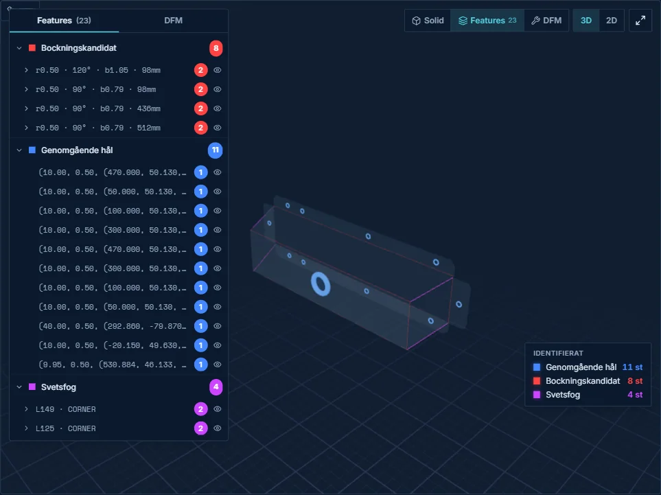
In Glintify's Geometry Viewer the bends are read from the STEP file. Every bend gets length, angle, inside radius, direction and type. Hems between roughly 150 and 210 degrees are classified separately so they are not counted as ordinary 90 degree bends. The basis is geometric. A bend that only exists as text on the drawing does not appear until someone adds it.
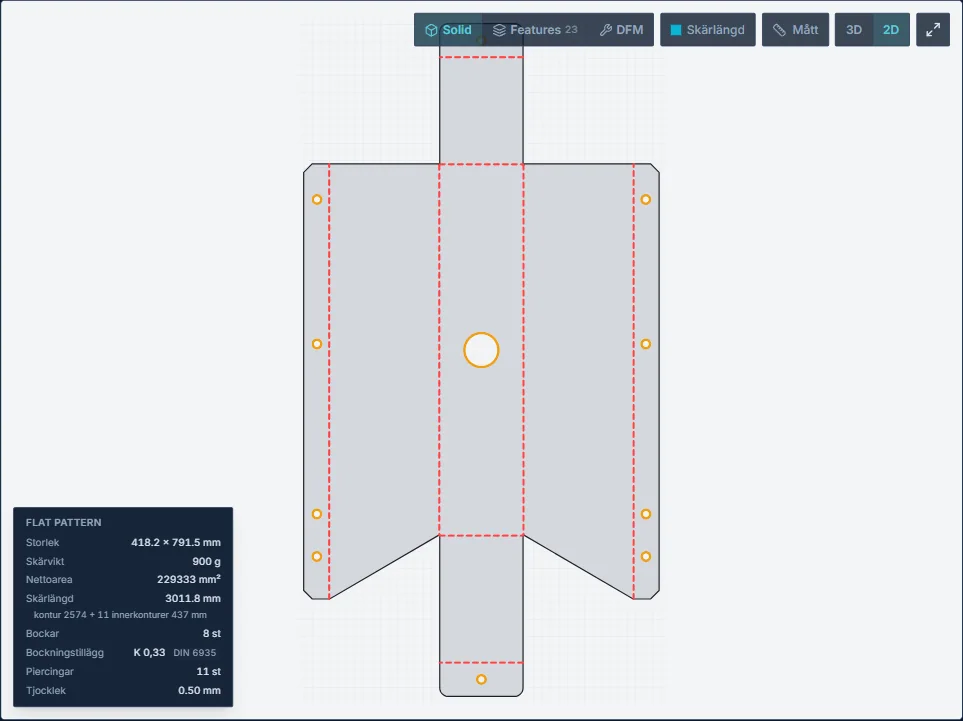
The unfold gives the blank, the bend lines and the cut length. The development is calculated with a DIN 6935 based compensation model that includes the ratio between inside radius and material thickness. For presentation the compensation can also be expressed as an equivalent K-value per bend. The same development sits behind the 2D view and the calculation, so the cut length shown cannot drift apart from the one that is priced.
Once your tool library and machine fleet are filled in, the chain continues. For a press brake the V-opening is selected against your dies and force is calculated per bend. DFM is tested against your tooling, and machines are ranked on cost at the requested quantity. Manual press, press with automatic tool changer, panel bender and robotised cell are four automation classes in the same economic choice, not four identical machine types. Without a library the V-opening is derived from a thickness ratio as a starting value and the tool-based DFM level is switched off. The price is not invented.
It is the same principle as in the rest of the bending calculation and in the laser and bending flow: the CAD file is measured, the calculation is built against your machines, and the estimator approves. How each line is traced is covered under cost calculation line by line.
When the estimator has to look
A measured bend list is a basis, not a running program. Several things are still decided by a human: springback and angle compensation for that specific batch, rolling direction, actual sheet thickness versus nominal, whether the first part should be test bent, and whether the robot can actually grip the part without damaging the surface.
Bend sequence, tool selection, collision checking and simulation can be done automatically by modern CAD/CAM systems. Geometry Viewer does not perform full tool, machine and sequence aware bend simulation in quoting mode. Wall height against punch working height can be secured as an upper limit, but without a known sequence there is no way to know which wall is standing at the last stroke. Collisions, repositioning and accessibility should therefore be treated as review points. The module sends no programs to the machine.
The system calculates. The estimator approves.
Five questions before you promise a bending price
- Which bending technique is the calculation based on: air bending, bottoming or something else?
- If the calculation is press brake: which V-opening, which punch and which minimum flange apply for this material and this thickness?
- Is any press in the shop enough for the longest bend, the force and the blank format?
- How many tool changes are required, and is the setup spread over the quantity the customer is actually asking for?
- Is the part a candidate for robot bending, or do handling, gripping and first-part work force it back to a manual press?
Summary and next step
Bending is more than an angle in the quote. The bending technique decides how radius and force arise in the press brake. The bending chart is the starting map towards V-opening and flange, until your own tooling takes over. Robot bending is an automation class whose economics must be calculated on the actual part and quantity. Panel benders and robot cells are not automatically right just because they exist. Bent parts get the right price only when those measurements are visible and someone owns what geometry cannot answer.
If you want to see the chain on a part you have already quoted, you can book a calculation walkthrough with a STEP file and your own presses.
Frequently asked questions
What is sheet metal bending?
Bending is the operation where a flat sheet is formed along a bend line so that flanges, U-profiles, boxes and similar shapes arise. In most companies it is done in a press brake with punch and V-die. A robot cell uses the same bending principle but handles the part automatically. A panel bending centre works with a manipulator and bending blades. The price is driven by bend length, number of bends, tooling, setup and how the part is handled, not by the angle alone.
What is a bending chart?
A bending chart links sheet thickness, and often material, to a recommended V-opening, approximate inside radius, minimum flange and sometimes tonnage. It is a starting value for air bending in a press brake. It does not replace your tool library or the tool maker's data, and it does not automatically apply to high-strength steels, stainless or aluminium.
What is the difference between air bending and bottoming?
In air bending the radius is mainly set by the V-opening and the angle is adjusted with punch depth. In bottoming the sheet is pressed against the die shape so the angle is locked harder. Air bending takes less force and handles several angles in the same tool. Bottoming costs more tonnage and more wear, but can hold a tighter angle.
When does robot bending pay off?
When the part can be gripped and run in the cell, and when setup, cycle time, staffing and rate give a lower cost at the requested quantity. Robotisation does not automatically give shorter cycle time. On some parts an experienced operator is faster, on others the cell is. The major economic advantage often lies in automated handling, a stable process, lower staffing and the option of unmanned or lightly manned running.
How do you calculate bending force?
For air bending in a press brake the common approximate model is P in kN per metre equal to 1.42 times tensile strength times thickness squared, divided by the V-opening. Multiply by the bend length in metres. The same 3 mm bend can therefore require more than double the force if the material changes from mild to high-strength steel, even with the same V-opening. Tool and machine tables and your own validated data take precedence over the generic model.
Why are bent parts more expensive than flat ones?
A flat part pays for cutting and material. A bent part also pays for setup, cycle time per bend, tool changes, handling and sometimes extra review when flanges, holes or radii sit close to the limit. That is why two parts with the same cut length can end up with completely different quotes.
Send in a STEP file for a bent part you have already quoted and compare your bending line against measured length, V-opening and machine choice.
Book a calculation walkthrough